My Inventions
With my broad passion in STEM, mechanical engineering has always been at the forefront of my fascinations. Over the years, I've undertaken numerous personal projects in anything from improving and refining existing products to designing/inventing and implementing new concepts completely. This page is dedicated for notable innovations that I've made, including one that is officially patented by me. Interested? Read more below!
Patented Slide
 Throughout my journey within FTC Robotics, one thing that has been used consistently every season are slider mechanisms.
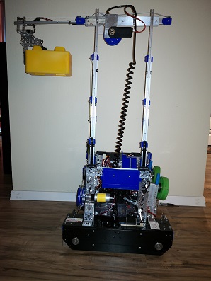
Sliders were exceptionally crucial in the 2019-2020 Skystone season, where the primary objective was to stack blocks into
high towers (teams layered several stages of slides together to optimize their robots for this purpose). However, what is
found on the market at the moment have a lot of weaknesses and issues that makes using them unreliable and ineffective. In Skystone,
extending multiple stages out to stack at great heights (as pictured) caused for the entire lift to be very shaky,
and often times resulted in knocked down towers (tremendous loss of points). Throughout the season, we tried over
4 different types of slides, but none of them were close to ideal for use. Knowing this, I did extensive research
and brainstorming, and eventually decided to work on designing and manufacturing my own drawer slides, with an
innovative design that eliminates the biggest problems found originally. Combined with custom designed pulley holders, the final assembly created a
clean, compact system, with easy maintenance for effective use in competition themes year after year.
Throughout my journey within FTC Robotics, one thing that has been used consistently every season are slider mechanisms.
Sliders were exceptionally crucial in the 2019-2020 Skystone season, where the primary objective was to stack blocks into
high towers (teams layered several stages of slides together to optimize their robots for this purpose). However, what is
found on the market at the moment have a lot of weaknesses and issues that makes using them unreliable and ineffective. In Skystone,
extending multiple stages out to stack at great heights (as pictured) caused for the entire lift to be very shaky,
and often times resulted in knocked down towers (tremendous loss of points). Throughout the season, we tried over
4 different types of slides, but none of them were close to ideal for use. Knowing this, I did extensive research
and brainstorming, and eventually decided to work on designing and manufacturing my own drawer slides, with an
innovative design that eliminates the biggest problems found originally. Combined with custom designed pulley holders, the final assembly created a
clean, compact system, with easy maintenance for effective use in competition themes year after year.
Issue 1: Wobbling
Traditional Slides
Ball bearings are all concentrated towards the center leaving the sides with nothing to hold the inner and outer slider together, creating wobbliness on the ends of the inner slide. This wobbliness occurs in four directions: in and out as well as up and down the screen you are looking at.
My Solution
Taking the normal bearings at the middle of the slider assembly, I split out 2 sets of stationary bearings for each end to help hold the slider together more securely. This allows for little to no wobble room no matter if the slider is fully retracted, extended, or anywhere in between while not losing any length in extending.
Issue 2: Total size
Traditional Stacking Methods
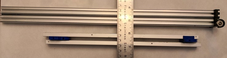
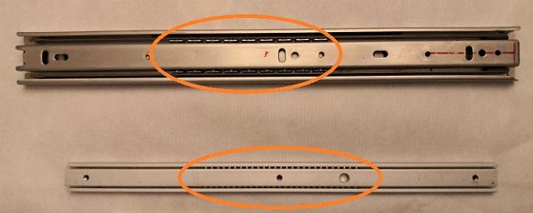
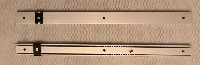
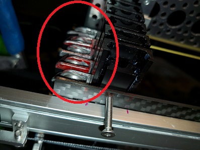
Traditionally, to stack slides together (necessary to achieve long extension distances) would take up absurd amounts of space. Two of the most used type of sliders, as pictured above demonstrate this claim clearly (1 inch and 1.5 inches thick for 2 stages, respectively), as the upper slider is inherently big in size, and the bottom slider requires the use of bulky pulley holders. As more slides are being stacked, this issue becomes more and more prominent.
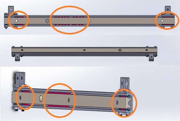
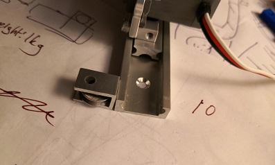
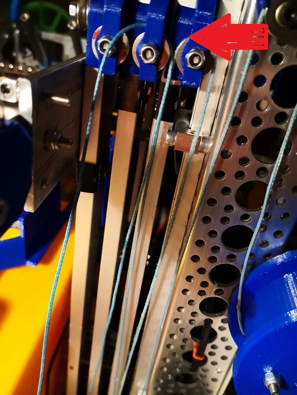 Traditional pulley holders are extremely bulky as pulleys are mounted horizontally, requiring a lot
of clearence to avoid adjacent pulleys from contacting each other, as addressed with the red arrow to the left.
Traditional pulley holders are extremely bulky as pulleys are mounted horizontally, requiring a lot
of clearence to avoid adjacent pulleys from contacting each other, as addressed with the red arrow to the left.
My Solution

My design involves creating new external pulley holders that are mountable on the sides of the sliders that allows pulleys to be mounted vertically. This means large amounts of space could be saved as sliders can be stacked back to back now (0.5 inches thick for 2 stages). This is incredibly important as we need more extension while leaving more space for other purposes.
Issue 3: Replacement Difficulty
Traditional Stacking Methods
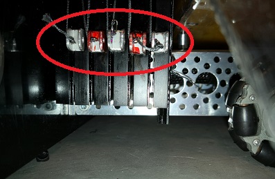
Due to how the pulley holders are mounted traditionally, to replace the pulley holde r with the red arrow in the above image, for example, would require the removal of all the slides/holders to the left of it. This is a huge hassle to do and also takes an immense amount of time in the process.My Solution
As addressed in Issue 2 above, the invention of external pulley holders mounted onto the sides of the sliders allows for each holder to be individually replaced, saving time and efforts tremendously.Issue 4: Accessory Customizability
Traditional Sliders
Traditional pulley holders are not only big such that they take up space, but they also do nothing besides hold the pulleys for the string. Overall, not a good use of space at all.My Solution
The pulley holders that I designed, furthermore, intricately allow for repurposeing to mount essentially any other accessories that the consumer deems necessary. Simply remove the pulley holder and swap it with whatever accessory is desired.My Patented Slide Design Evolution
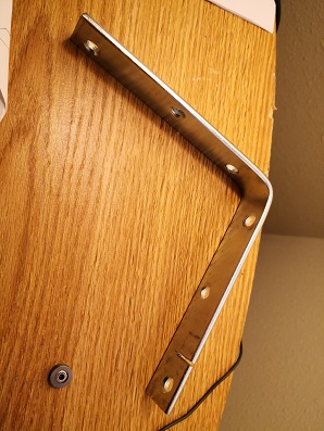
Evolution #1- Resolve wobble
This was the start of it all - In order to limit the amount of room the inner slider had to fall out in (the most obvious direction of wiggle room), I wrapped sliders with a black metal piece (pictured above). It certainly wasn't perfect (around a 25% wobble decrease) largely due to the fact that it only helped limit the wobbling on the left side of the sliders pictured here. However, this improvement was not applicable for the wobbling in the other three directions acknowledged above in "Issue 1" as caused by design conflicts in stacking sliders. As the first competition was coming up, we had no time to brainstorm and implement better solutions to this issue, and instead, had to settle for the descibed concept here. The important thing is that it was a good start for what's soon to come.
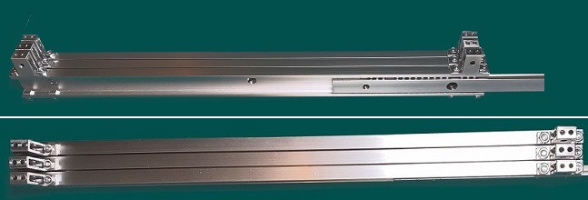
Evolution #2 - Redesign a new and compact pulley holder
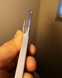
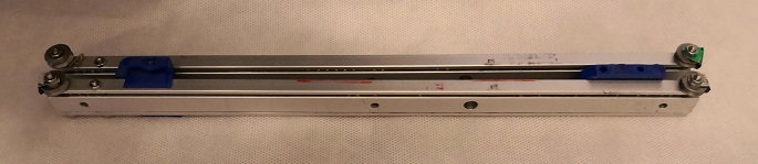
Custom made pulley holders that are compact - size was reduced enough to be as thin as a drawer slider itself - made possible with vertically mounted pulleys (traditional mounting took up much more room due to horizontal mounting).
Finished result after repeating the process of making my custom pulley holders
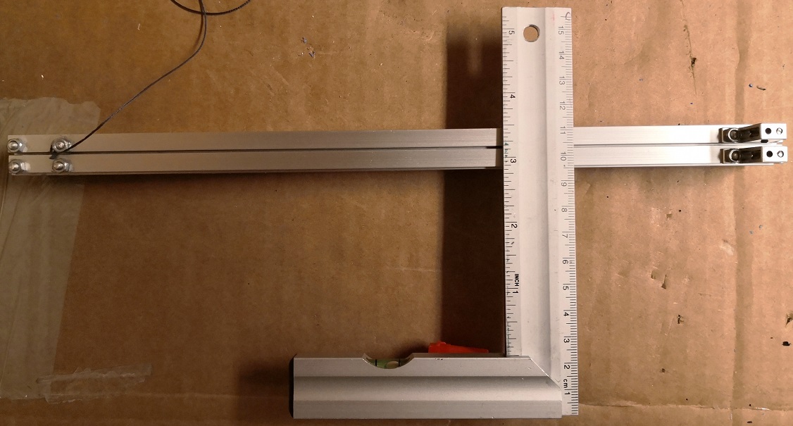
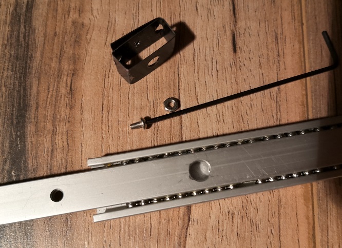
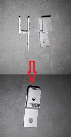
Due to a lack of effective equipment such as a CNC machine, I had no choice but to make everything by hand with materials that
are as close to ideal as possible. Fortunately, I came across an "H-Bracket" piece that was able to be modified
to fit our needs, but this needed me to make a molding tool (pictured left) to effectively create custom pulley holders the way I desired.
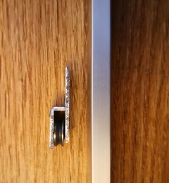
Above mentioned custom pulley holders mounted onto slides. Saves a lot of space as they are both external and allow for the pulleys to stack vertically.This was my first idea to resolve the pulley holder taking up space issue.
Evolution #3 - Resolve wobble

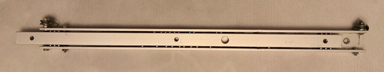
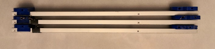
Knowing the flaws with "Evolution #1 - Resolve wobble" for resolving the wobble issue, I shifted my focus on making both ends secure as opposed to just one. As mentioned beforehand, the concentration of bearings at the middle of the slider was the main cause for slider wobbliness. So, the inclusion of stationary bearings on either end eliminiated the issue of wobbling in the sliders essentially completely. This is the first attempt I made in creating stationary bearings on the ends. I drilled and tapped holes on either end for screws, and used the screw heads to trap sets of 3 bearings on each side. This proof of concept helped justify my idea for solving the wobble issue. Moreover, although it did the job, it stilll led me to make a few more iterations for the sake of refinement.
Evolution #4 - Version 1 Design for patent application
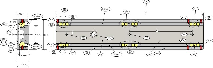
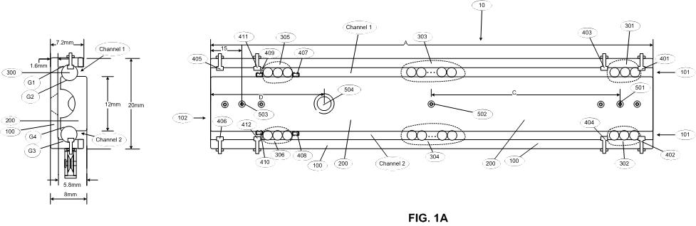
As seen in the prior stage ("Evolution #3"), the concept of adding stationary bearings on both sides proved to be successful, and I made the decision to take this concept to the next step: a patent. That preceding solution was merely a matter of modifying presently commercial slides. From there, my next step of refinement was to properly sketch out an all new, for-manufacturing design (see above). These sketches were also used to file my provisional patent for this drawer slider concept.
This design made use of threaded stoppers on both sides to hold stationary bearings on each end, with the threading intended for the mounting of external mechanisms such as my custom made pulley holder. Although conceptually sound, reaching out to manufacturers to quote production costs informed me that this sort of stopper was not cost efficient (in terms of assembly) and sturdy. With this information, it was (kind of) back to the drawing board.
Evolution #5 - Version 2
The next solution for stoppers that I had was just a slightly modified, factory produced version of "Evolution #3" with the use of screws that were screwed in from the outside to hold the stationary bearings on each side. On top of the outer slide was extra molded bits to help strengthen the screw inside the slider, while also providing a stub for external mechanisms such as my custom made pulley holder to mount on. Again, the concept seemed great; everything seemed sturdy and well thoughtout, so I rendered the entire assembly out in CAD software. But after consulting price quotes with factories, we learned that this again was incredibly cost inefficient (required them to create new molds which would be overwhemlingly expensive). Knowing this, I directed my attention towards achieving my desired results in a way that was manufactureable with current slider molds.
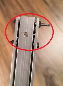
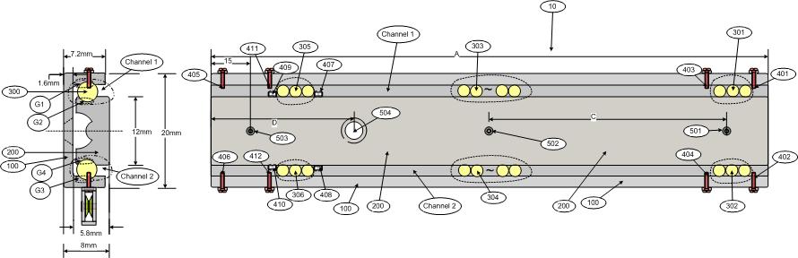
Evolution #6 - Final Production Version
For the sake of using current slider molds, it meant that I could not have any newly molded protrusions on any piece of the slider - cutting, holing, filleting, chamfering, etc. sort of things were all fine. Taking this into account, I came up with my third (and thus far final) design for this slider. I designed an intricate multipurpose screw that served as a stopper for the bearings and the source of mounting for accessories such as my custom pulley holder. These screws fit snuggly within the channel formed between the inner and outer slider, as seen above. The use of these screws preserved all of the novelties that I required, made certain things better (easier customizability) and yielded reasonable manufacturing costs. Since then, this design has been used for manufacturing and soon to be marketing. These sketches were applied in my non-provisional patent for these drawer sliders.
Root Service Product - Moss Cleaner |
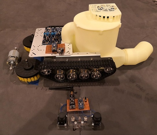
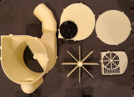
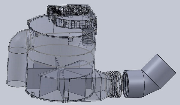
Dating back to August of 2019, after a long period of research and brainstorming, I started on a project to develop a moss cleaner robot (see above for prototype images). The reasoning behind this is from personal experience, as living in the rainy Pacific Northwest meant excessive amounts of moss collected on rooves. Up till date, there has not been any effective, safe way to clean the moss off. This small tank moss cleaner robot is made to fix just that - consumers can simply deliver this robot onto the roof and clean everything via remote controlling. This would not only eliminate the risk factor of humans ascending rooves, but also largely reduce the expenses and time needed to complete such a commonly reoccuring task. My intentions were to build a remote controlled (with live video feed) robot to clean moss, leaves, tree branches, etc. as well as to dispense moss killer. This was the first of a series of three different roof servicing robots including a custom built drone to deliver the robot onto the roof itself. Unfortunately, due to lack of time from school as well as a shift of focus towards competitive robotics, this project has been placed on hold for the foreseeable future. Should anyone be interested in contributing to this concept, please reach out to me, and we can make it happen someday! |
2-Speed Robot Wheel Gearbox |
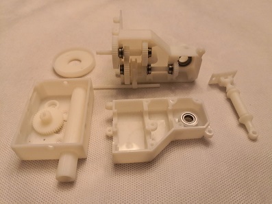
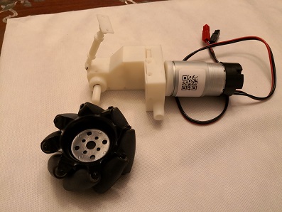
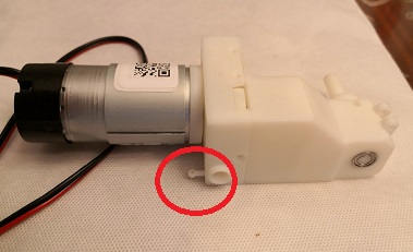
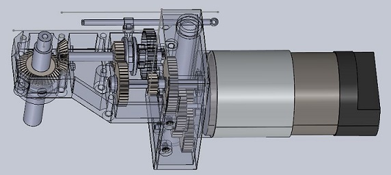
No matter what the objective is, and no matter what robot is being made, it cannot avoid the need for a drivetrain. For competitive robotics, teams frequently will design new drivetrains season after season to fit the objective as best as possible, which is an extremely time consuming process for the limited period of time given already. To avoid this, the intention with this project was in line with creating a "one-size-fit-all" adaptable drivetrain that could be used in any sort of competition theme. This gearbox provides a compact solution in bringing 2 different, adjustable output speeds (allowing for both speed and torque intensive tasks) as well as a suspension system to conquer any sort of field terrain. Above are prototype models of my design, and through testing, has seemed to be successful. |